In this post I'll show you about the ESP8622 wi-fi module & how to configure the ESP8622 wifi module.In here we are using the esp-01 version.What this module does is connects the arduino module with the internet via wi-fi.Below is the pin output diagram.

This module have 8 pins.But we are using only 5 pins for this project.And those are working as below,
VCC
This is the power input for this module.And this module works with a 3.3v power.So we need to give a +3.3v to this pin.
GND
This is the ground input pin of this module.And we need to connect - power to this pin.
CH_PD
To activate this module , we need to connect a + 3.3v connection to this pin.
RXD
This is the data receiving line for this module.And this pin connects with the TX pin of the Arduino board.
TXD
This is the data transmitting line for this module.And this pin connects with the RX pin of the Arduino board.
To configure this module we should have ,
- FTDI USB to Serial converter
- 5v to 3.3v dc-dc converter
- Jumper wires
Now I'll show you how to wire this module with the FTDI module for configuration.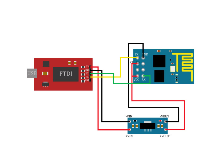
- FTDI Adapter +5V Pin to 5V to 3.3V DC to DC Converter +VIN Pin.
- FTDI Adapter GND Pin to 5V to 3.3V DC to DC Converter -VIN Pin.
- 5V to 3.3V DC to DC Converter +VOUT Pin to ESP8622 VCC Pin.
- 5V to 3.3V DC to DC Converter -VOUT Pin to ESP8622 GND Pin.
- 5V to 3.3V DC to DC Converter +VOUT Pin to ESP8622 CH_PD Pin.
- FTDI Adapter RX Pin to ESP8622 TX Pin.
- FTDI Adapter TX Pin to ESP8622 RX Pin
After we connect all the pins as above , we need to connect the FTDI module to the computer using a data cable.Then open the device manager in the computer.

Then under the ports , the FTDI module will show.And note down the COM port address ,in here it is COM4.
Then open the Arduino IDE.


Then open the Arduino IDE.
Then go to Tools > Port , then select the port name which was showing in the device manager.And that is the FTDI module.
After that open the serial monitor of the Arduino IDE (Ctrl + Shift + m).
As following image we need to select the settings(In some modules baud rate comes as 9600 & in some it comes as 115200).
Then type as "AT" in the command field & hit enter.If the module is working good & the connections are correct , we should get a message as "OK". If not we have to check the pin connections & the selected COM port.After that send a command as "AT+GMR". Then it will show us the firmware version.
In my case , this module's firmware version is 001800902.If the module's firmware is below than 902 , we have to upgrade the firmware.
In next post I'll show you how to upgrade the ESP8622 module firmware.


0 comments:
Post a Comment